A thin converging lens, often referred to as a convex lens, focuses parallel rays of light to a single point known as the focal point. This action occurs because the lens is thicker at its center than at its edges, causing light rays to bend towards the axis as they pass through. When a parallel beam of light (such as sunlight) enters the lens, each ray is refracted at both the air-to-lens and lens-to-air interfaces. The degree of bending depends on the curvature of the lens surfaces and the refractive index of the lens material. As a result, all parallel rays converge at the focal point on the opposite side of the lens, a distance known as the focal length.
Features of a thin converging lens include:
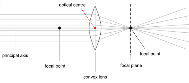
The focal length of a lens is the distance between the lens and the focal point, where parallel rays of light converge after passing through the lens.
For a thin converging lens, the focal length is the point where parallel rays of light that enter the lens converge to a single point on the opposite side. The focal length depends on the curvature of the lens surfaces and the refractive index of the lens material.
Follow the following steps to draw ray diagrams for a thin converging lens:
Explore, using the simulation below, the characteristics of the image formed when the object is placed at different distances away from the lens.
| Object Position | Image Position | Image Nature | Image Size | Image Orientation | Examples |
|---|---|---|---|---|---|
| At infinity | At focus (F) | Real | Diminished (point size) | Inverted | Sunlight focused by a magnifying glass |
| Beyond 2F | Between F and 2F | Real | Diminished | Inverted | Object viewed through a camera lens |
| At 2F | At 2F | Real | Same size | Inverted | Object at twice the focal length of a projector lens |
| Between F and 2F | Beyond 2F | Real | Magnified | Inverted | Slide being projected onto a distant screen |
| At focus (F) | At infinity | No image | Infinite size | Inverted | Object at the focal length of a lens, no clear image formed |
| Between lens and F | On the same side as the object | Virtual | Magnified | Upright | Object viewed through a magnifying glass |
Real images are formed when light rays converge and actually intersect at a point after passing through the converging lens. Real images are usually inverted relative to the object. These images can be projected onto a screen because the light rays physically converge at a point.
Virtual images are formed when light rays diverge, and the image appears to be at a location from which the light rays appear to come. The light rays do not actually meet but seem to diverge from a point behind the lens. Virtual images are typically upright relative to the object. These images cannot be projected onto a screen because the light rays do not actually converge at a point. The image can only be seen by looking into the lens.